
| Fort McHenry Tunnel - Construction - 1984 |
The following 21 photos are of various stages of the construction of the Fort McHenry Tunnel in Baltimore, Maryland.
Click the small image to link to a larger image (they range in size from 90K to 180K).
| Fort McHenry Tunnel - Construction - 1984 |
The following 21 photos are of various stages of the construction of the Fort McHenry Tunnel in Baltimore, Maryland.
Click the small image to link to a larger image (they range in size from 90K to 180K).
| This group of 12 photos was taken of the West Approach and East Approach construction, on same day in February 1984, in the same photo session. |
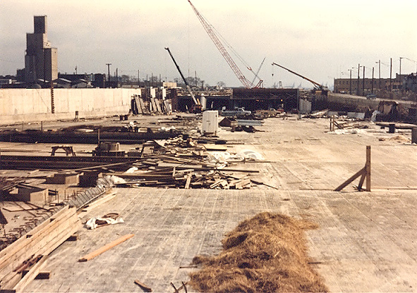 |
West approach construction. I'm standing on the highway near where the highway reaches ground level, looking eastward down the open approach, and the four tunnel portals are in the distance. |
 |
West approach construction. I'm standing on the highway near where the highway reaches ground level, looking eastward down the open approach, and the four tunnel portals are in the distance. Same vantage point as the previous photo, but with a 135mm (2.7x) telephoto lens instead of the 50 mm (1.0x) regular lens used in the previous photo. |
 |
West approach construction. I'm standing behind the retaining wall at the edge of the depressed approach, looking toward the four tunnel portals. |
 |
West approach construction. I'm standing near where the sunken tubes connect to the cut-and-cover tunnels, looking westward. The tunnel portals are just beyond the cranes. |
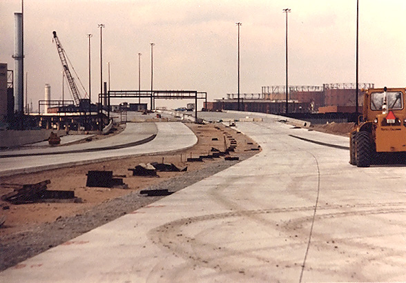 |
West approach construction. I'm standing on the highway near where the highway reaches ground level, looking westward. Concrete pavement has been constructed for I-95 down the open approach, and the highway rises onto the elevated viaduct in the distance. Much of I-95 on the Locust Point Peninsula is on elevated bridge structure. |
 |
Sunken tube construction. I was walking around taking pictures of the East Approach construction, and the superintendent of the subcontractor's concrete plant saw me, and invited me to go down into the tunnel. We had to walk down about 70 feet of a temporary construction stairwell, and I got my first view of the interior of the Fort McHenry Tunnel! Thank you, Reds House, Jr. |
 |
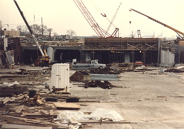
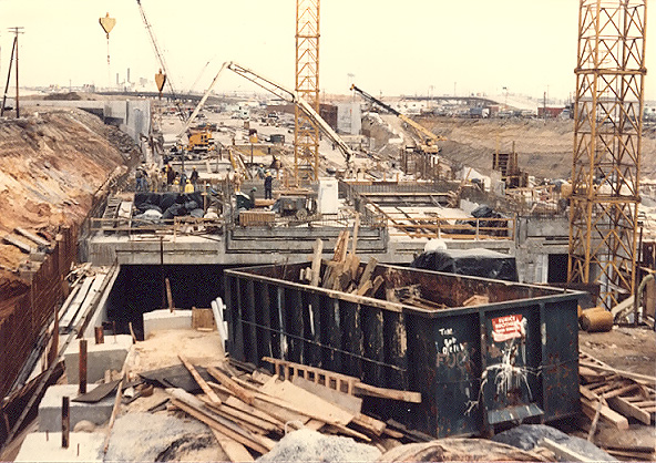
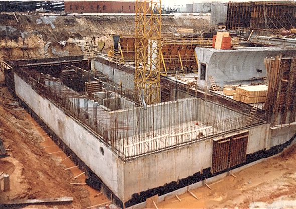
East approach construction. East end of the sunken tubes is on the right side of the photo, and cut-and-cover tunnel construction is underway. |
 |
East approach construction. I'm standing on top of the east end of the sunken tubes, looking east. |
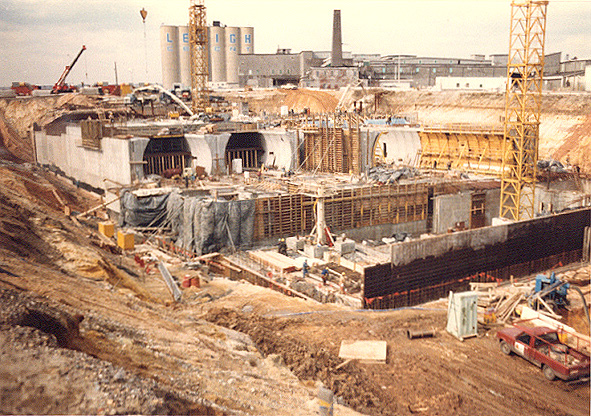 |
East approach construction. I'm standing on the south side of the highway construction, looking westward. The foundation of the East Ventilation Building is under construction in the center of the photo. |
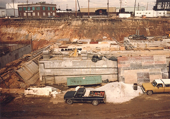 |
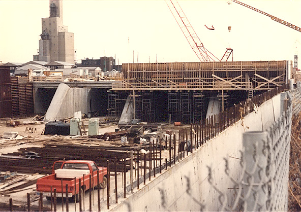
East approach construction. I'm standing on the south side of the highway construction, looking northward across the highway. Notice the concrete gravity slab in the center of the photo. The gravity slabs are constructed in massive monolithic concrete pours, and two joints can be seen on the gravity slab. To gauge the size of the gravity slab, compare it to the pickup truck that is parked about 20 feet from the gravity slab. |
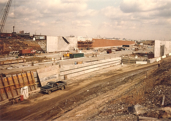 |
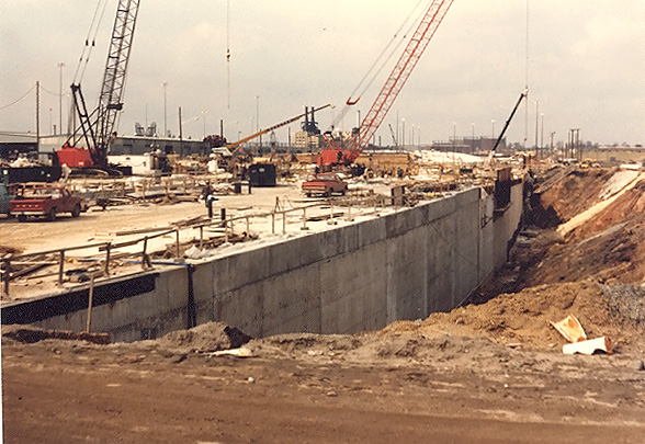
East approach construction. I'm standing on the south side of the highway construction, looking eastward across the highway. Notice the concrete gravity slab in the center of the photo. The retaining walls in the distance will support the earth as the highway descends below ground level, and the mainline toll plaza is under construction in the distance. |
 |
East approach construction. I'm standing on the south side of the highway construction, looking northward across the highway. The foundation of the East Ventilation Building is under construction in the center of the photo. Baltimore Harbor is to the left. |
Notice the massive concrete gravity slabs under construction in some of the photos. They will range from 7 to 20 feet thick, designed to resist the hydrostatic pressure below sea level; the thickness increases as the tunnel grade slopes downward toward the harbor, reaching about 30 feet below sea level where the sunken tube tunnel begins. The gravity slabs extend for the full width of the approach tunnel and open depressed approach, and they literally serve as an "anchor" by providing enough weight to prevent the structure from "floating" upward from the pressure of the ground water. The I-395 Mall Tunnel in the District of Columbia and the I-95 "bathtub" project in downtown Philadelphia used gravity slabs too, for the same reasons, where tunnels and open approaches were below sea level.
| This group of 9 photos was taken of the underwater tunnel (Trench Tunnel Contract) and East Approach construction, on same day in March 1984, in the same photo session. I was on an ASHE (American Society of Civil Engineers) field trip to the project. |
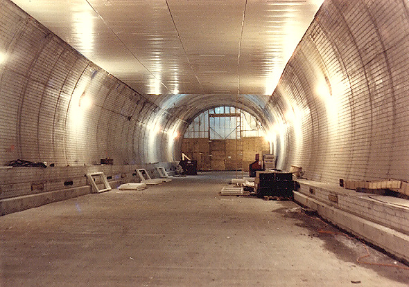 |
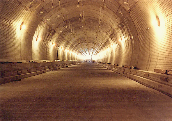
Underwater tunnel construction. I was standing on the two-lane roadway slab, looking toward a temporary construction bulkhead between two joined sunken tube elements. Prefabricated ceiling panels are being installed in the upper part of the tube. The space between the top of the tunnel invert and the ceiling structure, will be utilized as the exhaust air ventilation duct for the traffic tube, and the passageway runs the full length of the tunnel. There are slots in the ceiling panel for channeling the exhaust air from the traffic tube to the exhaust duct, but they are hard to see in these photos. |
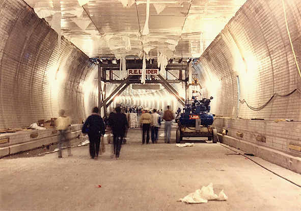 |
Underwater tunnel construction. I was standing in about the same spot as in the previous photo, but looking in the opposite direction (eastward) down the tunnel. We were about 1,000 feet from the western end of the tunnel. Prefabricated ceiling panels are being installed in the upper part of the tube, utilizing the placement vehicle/platform ahead. |
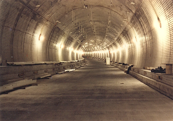 |
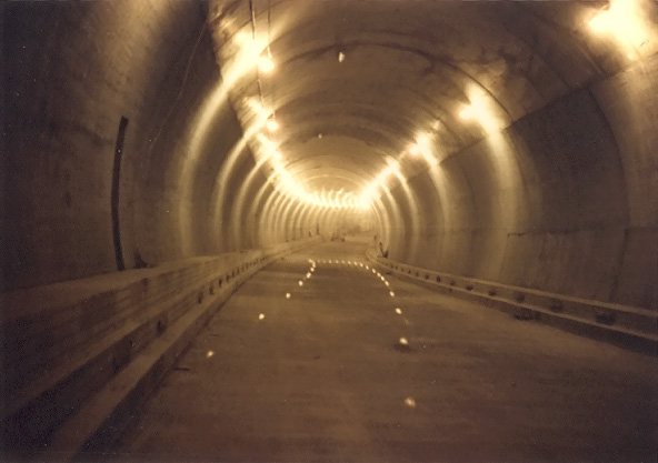
Underwater tunnel construction. Near the lowest point of the tunnel at mid-harbor. Most of the Fort McHenry Tunnel is built on a very gradual horizontal curve, about 1.5 degrees, with adequate sight distance for 70 mph traffic. The reason for the long gradual horizontal curve, was to avoid going through the Fort McHenry land. |
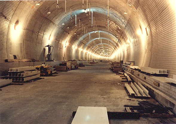 |
Underwater tunnel construction. Now we are about 1,000 feet from the east
end of the tunnel. Looking westward.
The hangers from the top of the tunnel invert, will support the
prefabricated ceiling panels when they are installed. Remember, the Fort McHenry Tunnel has four separate two-lane traffic tubes. |
 |
Underwater tunnel construction. I was standing in about the same spot as in the previous photo, but looking in the opposite direction (eastward) toward the east tunnel portal in the distance. |
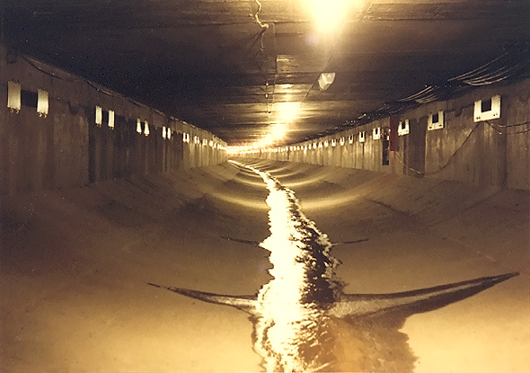 |
Underwater tunnel construction. I was in the same section of the tunnel as in the previous photo, but I am standing at the bottom of the tunnel invert, UNDER the roadway slab (all the other tube photos were taken while I was standing ON the roadway slab). This passageway runs the full length of the tunnel, and handles sump drainage, as well as being utilized as the intake air ventilation duct for the traffic tube. The slots for channeling intake air to the traffic tube above, are visible at the top of the wall just under the roadway slab. After the tunnel opens to traffic, at full ventilation capacity at this point about 1,000 feet from the end of the tunnel, the airstream through here will be moving at about 70 mph. |
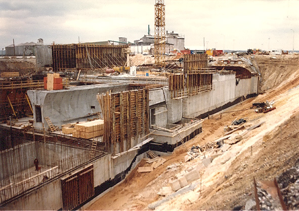 |
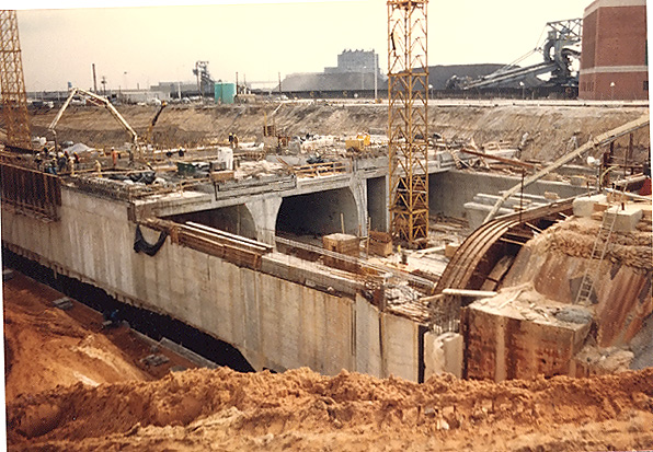
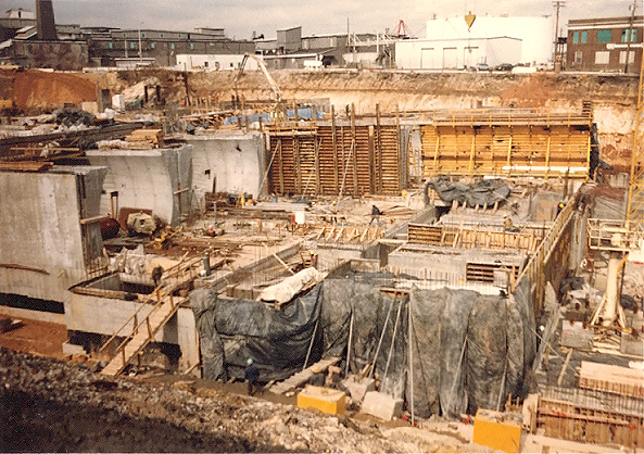
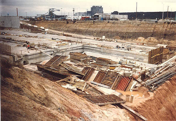
East approach construction. Cut-and-cover tunnel construction is in the foreground, and the end of the sunken tube tunnel is visible at the end of the trench. |
 |
East approach construction. I was standing in about the same spot as in the previous photo, but I turned somewhat to the left, to photograph the construction of the foundation of the East Ventilation Building. |
 |
East approach construction. I was standing in about the same spot as in the previous photo, but I turned more to the left. Notice the thickness of the concrete gravity slabs that are being constructed on the open approach. At that point, the gravity slabs are about 12 feet thick. |
Next: Fort McHenry Tunnel - Construction - 1985
All photos taken by Scott Kozel.
Copyright © 2003 by Scott Kozel. All rights reserved. Reproduction, reuse, or distribution without permission is prohibited.
Lead page for Fort McHenry Tunnel
- Construction
Lead page for Fort McHenry Tunnel
By Scott M. Kozel,
Roads to the Future(Created 1-1-2003)